Nullam dignissim, ante scelerisque the is euismod fermentum odio sem semper the is erat, a feugiat leo urna eget eros. Duis Aenean a imperdiet risus.
Nullam dignissim, ante scelerisque the is euismod fermentum odio sem semper the is erat, a feugiat leo urna eget eros. Duis Aenean a imperdiet risus.
 Eren
Process selection begins only after reviewing the actual workpiece and its coating specification.
Consider an open steel frame with direct access to its welds and external faces. Add a folded channel behind one crossmember and close one end: the material and factory remain unchanged, but the coating problem does not. The visible color may be straightforward; the narrow, corrosion-prone pocket is not.
This is the starting point for Colin’s e coating vs powder coating review. We manufacture both ED coating systems and powder coating lines. Our engineers use the component drawing as the primary review document. Useful detail includes sectional views, holes, weld locations, drainage features, and proposed hanging points.
Before comparing equipment, mark the drawing by function:
The term finish therefore represents three separate engineering requirements.
A front panel may need a smooth colored skin. The seam behind it may simply need reliable protection. A threaded hole needs neither. This little exercise is far more revealing than a list of generic coating advantages.
Then look for liquid traps. Could an immersed part fill and drain while hanging in the proposed position? Where would air stay trapped? Where can a rack touch bare metal without leaving an unacceptable mark? These aren’t small installation details. They affect whether electrodeposition is sensible in the first place.
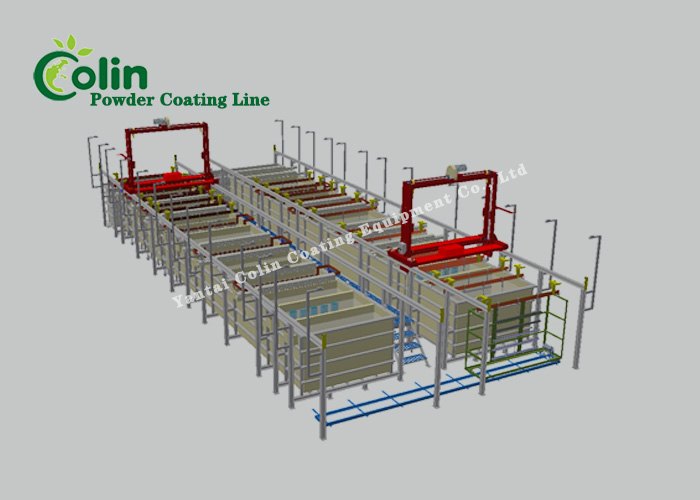
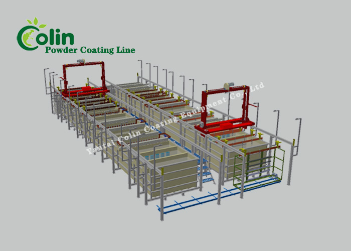
For an ED line, the working sequence is:
Oil, soil, or inadequate pretreatment remains a quality risk even when the electrical stage is correctly controlled.
Orientation can be assessed with a cup-shaped bracket. Opening upward, it retains liquid and increases carryover into the rinse section; turned on the rack, it drains differently. The early study therefore records rack contact, spacing, loading direction, and the path taken by liquid as the component leaves each tank.
Our pretreatment systems are planned as part of that route. An electrical bath cannot rescue poor cleaning. We also look at drainage, nonconductive sections, and the amount of masking the part would require.

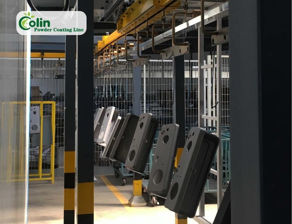
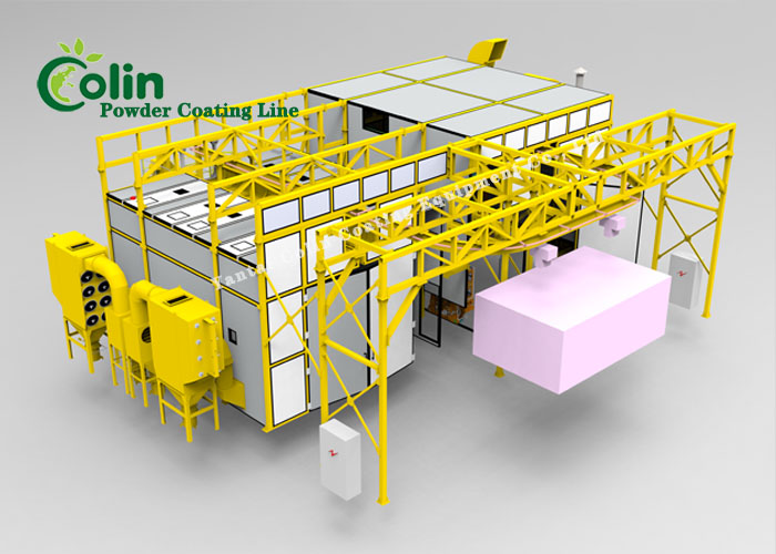
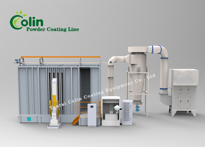
In the usual powder process, charged dry material is sprayed toward a grounded component and the deposited layer is cured by heat. The Powder Coating Institute provides a fuller description of this method.
Physical samples provide the reference for color, gloss, and texture. Manual guns suit some production mixes; reciprocators supported by touch-up suit others.
Spray access must be reviewed from the gun position. A deep corner behind a flange may receive insufficient powder while the exposed front face builds excessive film. Hanger position, gun angle, voltage, distance, and speed can improve the balance. Repeated touch-up at the same location may indicate that the original process choice requires review.
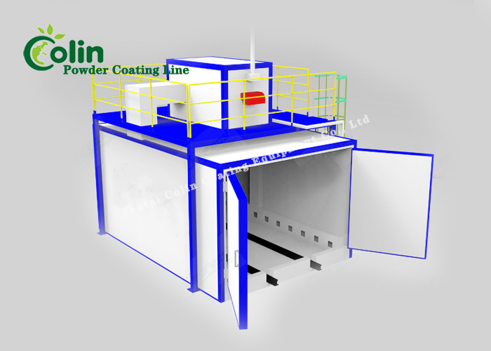
Curing introduces a further workpiece variable: thermal mass. A thin panel and a heavy casting on the same carrier heat at different rates. A powder coating oven review therefore needs four connected inputs:
The oven air display, by itself, does not verify cure at the metal surface.
Conductive seams and hidden recesses support consideration of e-coat. An open, customer-facing shell generally favors powder. Before approval, apply two geometry checks:
The operating comparison extends beyond energy consumption:
At sign-off, review the approved specification beside the drawing once more. Difficult geometry warrants an agreed coating trial and inspection method. Record the measured result, the inspected locations, and any accepted visual limit in the project file. The customer’s written requirement remains the final acceptance basis for production.
One workpiece can pass through both ideas. Electrocoat takes the primer role and reaches awkward conductive geometry; powder handles the visible outer finish. This is an established pairing—the Electrocoat Association lists powder among the topcoats used over electrocoat.
A two-layer route adds handling and requires one control plan for:
Those extra steps can be justified when the primer protects difficult geometry and the topcoat provides the approved exterior finish.

ED spreads through a chain of wet stages before the oven. Powder puts more of the action near the booth, recovery system, and color-change area. Around either one, draw the space people need—not just the steel they buy.
Colin prepares the 2D and 3D layout from both the workpiece and the workshop. On that drawing, the team checks rack turning, drainage above the tanks, access around the oven, conveyor movement, utilities, and maintenance routes before equipment positions are fixed.
Submit drawings or photographs for the smallest and largest parts. Include material, finish specification, output, available utilities, and workshop dimensions. Mark drain locations, masking areas, and acceptable rack contacts on the drawing. Colin can use the same package for the factory layout, foundation information, and utility interfaces.
Contact Colin with that information. We’ll compare ED, powder, and a combined route against your actual workpiece rather than guessing from its outside dimensions.
A: No. Recess coverage is one consideration among substrate preparation, film condition, service exposure, and the approved test requirement.
A ;It can. Electrocoat commonly takes the primer role while powder supplies the visible face. Material compatibility and the two cure steps remain part of the plan.
A: Begin with powder samples; their decorative range is normally wider.
A: No. The alloy and its pretreatment must be reviewed with the selected coating and test requirement.