Nullam dignissim, ante scelerisque the is euismod fermentum odio sem semper the is erat, a feugiat leo urna eget eros. Duis Aenean a imperdiet risus.

Sand Blasting Room Design Checklist for Buyers

  • Sand Blasting Room Design Checklist for Buyers Eren
  • 23rd October 2026

A stated enclosure size is only a starting dimension. The usable layout includes the largest workpiece, crane travel, loading clearance, and the operator’s hose envelope.

At Colin, we apply the following checklist when a sandblasting booth system reaches preliminary layout review. The marked workshop drawing can then accompany the RFQ.

1. Define the Workpiece and Blasting Target

Put both size extremes on the same page. Show the parts in the position used for loading and blasting—not their most convenient catalog view.

Workpiece notes

  • Smallest and largest dimensions
  • Maximum weight and center of gravity
  • Material and incoming surface condition
  • Lifting points, projections, pockets, and enclosed areas
  • Faces hidden after assembly
  • Actual carrier and lifting method, including the combined loading envelope
  • Permitted contact points and areas vulnerable to damage

Finish notes

  • What must come off the surface: rust, scale, weld residue, failed paint, or something else
  • Named cleanliness grade, where specified
  • Required surface profile
  • Inspection tool and acceptance method
  • Coating or pretreatment immediately after blasting

“Blast until clean” leaves too much unresolved. A written surface target lets production know when to stop and gives the equipment review a real duty to examine.
2. Door, Loading, and Operator Clearance

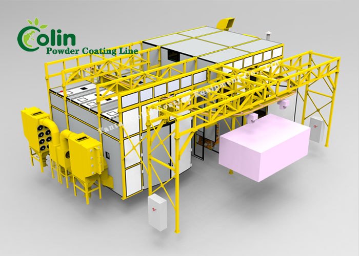
colin-sandblasting-booth

Trace one complete loading cycle. Begin in the factory aisle, not at the booth threshold.

At the main door

  • Clear opening checked against part andcarrier together
  • Outside approach long enough for the rail cart
  • Forklift turning and reversing space shown
  • Crane hook travel drawn at working height
  • Door swing, seals, track, and floor transition kept clear
  • Safe personnel entry available after the load is parked

Around the parked workpiece

  • Operator stance shown at front, rear, and both sides
  • Hose route free from sharp turns and trapping points
  • Underside reachable without unsafe posture
  • Heavy fabrication not dependent on repeated manual turning
  • Lights and viewing windows outside direct abrasive rebound
  • Liners protecting predictable high-wear areas

Check the drawing with the largest part first. Add the hose route and bring the loading equipment through the door. Confirm the room dimensions only after these operating clearances have been verified.

3. Plan Airflow and Dust Control

Indicate the proposed air path from the inlet openings toward the exhaust, with the normal load shown in its operating position.

Questions beside the arrows

  • Quiet pocket behind the load?
  • Dust crossing the breathing zone before reaching exhaust?
  • Open main door reversing the intended direction?
  • Inlet or light exposed to direct blasting?
  • Dust leakage toward nearby production areas?
  • Useful visibility at the surfaces being cleaned?

Record the expected airborne mixture before collector selection:

  • Abrasive fines
  • Rust and scale
  • Base-metal particles
  • Fragments of the previous coating

These inputs belong in the hazard assessment and waste plan as well as the ventilation review.

Two useful references belong in the design file:

  • US general industry: OSHA 29 CFR 1910.94, including blast-room exhaust, collection, respiratory protection, and recirculated-media separation
  • UK guidance: the HSE local exhaust ventilation guide, with the room treated as a full enclosure below surrounding workplace pressure

Project-specific inputs for the final ventilation review

  • Room volume and door openings
  • Typical load position
  • Abrasive and removed contaminant
  • Nozzle count and blasting duty
  • Duct route and discharge conditions
  • Local exposure, environmental, and fire requirements
  • Operator breathing air and selected respirator arrangement

The references are not a universal fan schedule. Room, hazard, and local law still have to meet in the final calculation.

Check compressed air separately. Record nozzle size and count, pressure, simultaneous use, hose length, compressor free-air delivery, receiver capacity, and treatment for clean, dry air. Motor rating alone does not confirm production nozzle pressure.

4. Abrasive and Recovery

Despite the familiar name, the room may never see ordinary sand. Put the intended medium on the specification—perhaps steel shot or grit, a mineral abrasive, glass bead, or another approved choice.

Abrasive record

  • Required cleaning action and profile
  • New or reusable medium
  • Expected breakdown and dust
  • Risk of contaminating the workpiece
  • Storage and filling method
  • Disposal route for spent material and debris

Shift record for recovery sizing

  • Approximate abrasive quantity reaching the floor
  • Main accumulation zones
  • Return or removal frequency
  • Cleanup time between loads

Recovery check

  • Manual cleanup acceptable between loads?
  • Partial or full floor collection?
  • Likely transport concept under the floor and up to separation?
  • Foundation depth and building work available?
  • Separator reachable for adjustment and service?
  • Return route to the blast pot short and protected?

Collector and separator are two different boxes on the process drawing. The first belongs to exhaust air. The second keeps unwanted fines and debris out of the returning abrasive.

At low utilization, a flat floor with manual cleanup can be reasonable. Higher operating hours change the calculation: repeated labor and lost loading time are then compared with the cost of partial or full recovery.

5. Provide Maintenance Access and Safety Controls

When the operator route is complete, repeat the layout review for maintenance. Filter withdrawal, liner replacement, duct inspection, cleanup, and repair each need a defined access path.

Service-space notes

  • Filter-removal direction shown
  • Access to ducts, conveyors, elevator, and separator
  • Worn liner removable without dismantling unrelated equipment
  • Lights and viewing panels replaceable from a safe position
  • Clean route for collected dust and used abrasive
  • Electrical panels clear of the parked workpiece

Safety review ownership

  • Door and equipment interlocks
  • Emergency stops
  • Grounding and static control
  • Operator communication
  • Entry and rescue procedure
  • Air supply for the respirator
  • Protection chosen for breathing, impact, hearing, and the body
  • Applicable inspection and training records

For US projects, the OSHA rule cited above requires approved respiratory protection for an operator inside a blast-cleaning room, together with dust and impact protection. The site hazard assessment determines the complete measures.

6. Protect the Prepared Surface

automatic-spraying-pretreatment-system

The drawing should continue beyond the exit. Freshly blasted steel can quickly lose its clean start.

Downstream check

  • Inspection point immediately after blasting
  • Loose-dust removal method
  • Clean lifting gear
  • Maximum allowed waiting condition or interval
  • Incoming traffic separated from prepared parts
  • Covered route to the next operation

Where chemical pretreatment also appears in the approved process, write the correct order on the route. A blast room feeding a powder coating line also needs a clean place to inspect and transfer the prepared part.

Information Required for the RFQ

metal-powder-coating-line

A useful RFQ follows the workpiece through blasting and onward to coating. Attach the part drawings and provide:

  • Weight and incoming condition
  • Surface target and inspection method
  • Output and chosen abrasive
  • Handling route and available utilities
  • Floor loading, pit limits, roof height, power, compressed air, make-up air, exhaust route, and waste provisions
  • Destination after blasting and the next finish

With those inputs, Colin can develop a custom finishing solution around the enclosure, handling, ventilation, recovery, controls, and onward flow. Colin can issue factory-layout, foundation, and utility-interface requirements, then support commissioning and maintenance training within the agreed scope. Send us the workpiece and workshop package before fixing the room dimensions.

Frequently Asked Questions

Q: How should clearance be set for different workpieces?

A: Use the largest operating envelope, then verify the operator position, hose route, loading method, lighting, doors, air openings, and service access.

Q: Why are air blast and wheel blast quoted differently?

A: One sends media through a nozzle with compressed air; the other throws metallic media from a mechanical wheel. The part and production target decide which discussion to have.

Q: Does every room need automatic recovery?

A: No. Start with weekly operating hours and the acceptable cleanup delay, then price labor, floor work, reuse, and contamination control.

Q: Are dust collection and abrasive separation the same duty?

A: Specify the duties separately. The collector treats exhaust air; the separator cleans media returning to the blast process.


Tags:

Table of Contents

Frequently Asked Questions

We provide customized solutions. Please inform us of your workpiece material (such as iron, aluminum), maximum/minimum size, weight, shape complexity, and expected coating thickness and quality requirements. We have extensive experience in handling various workpieces and will provide the best design solutions.
The prices of production lines vary greatly due to differences in production capacity, automation level, configuration, and energy types. A basic semi-automatic line may start at tens of thousands of dollars, while a fully automated large-scale line may exceed hundreds of thousands of dollars. We provide free consultation services, and after understanding your specific needs, we will provide detailed solutions and transparent quotations.
Our standard quotation usually includes host equipment, domestic shipping costs, installation and commissioning, on-site operation and maintenance training. The foundation of the factory building, external water, electricity, and gas pipeline connections, lifting tools, and local approval fees are usually the responsibility of the customer. We will provide detailed site preparation guidelines and interface requirements, and list all items in the contract without any hidden costs.
The typical installation and debugging cycle is 4-8 weeks, depending on the complexity of the production line. The factory building needs to provide stable electricity (voltage/power), compressed air (clean and dry), and necessary exhaust channels. We will provide detailed factory layout and foundation drawings in advance, and dispatch engineers to provide on-site guidance
We provide a one-year warranty for standard equipment, with longer warranty periods for core components such as electrostatic generators and PLCs. We provide 24/7 online technical support. For emergency faults, we promise to respond within 2 hours and quickly resolve them through remote guidance or coordination of local service resources. We have service outlets/partners in major markets.
Latest Product

Check out our Product

View More
about--300x300
Yantai Colin Coating Equipment Co., Ltd

Ask for More Solutions

Colin is committed to providing customized spraying solutions based on customer needs

    Your Name

    Email*

    WhatsApp*

    Message*

    Products
    Contacts
    WhatsApp
    Email